Explore how PMI-techria sources precision components for automation, material handling, and assembly teams—from the first drawing line to a production-ready motion system.
Each case study begins with the supplied engineering drawings, then shows the selected components and the 3D assembly. Click any 3D card below to load the STEP file in-browser.
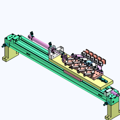
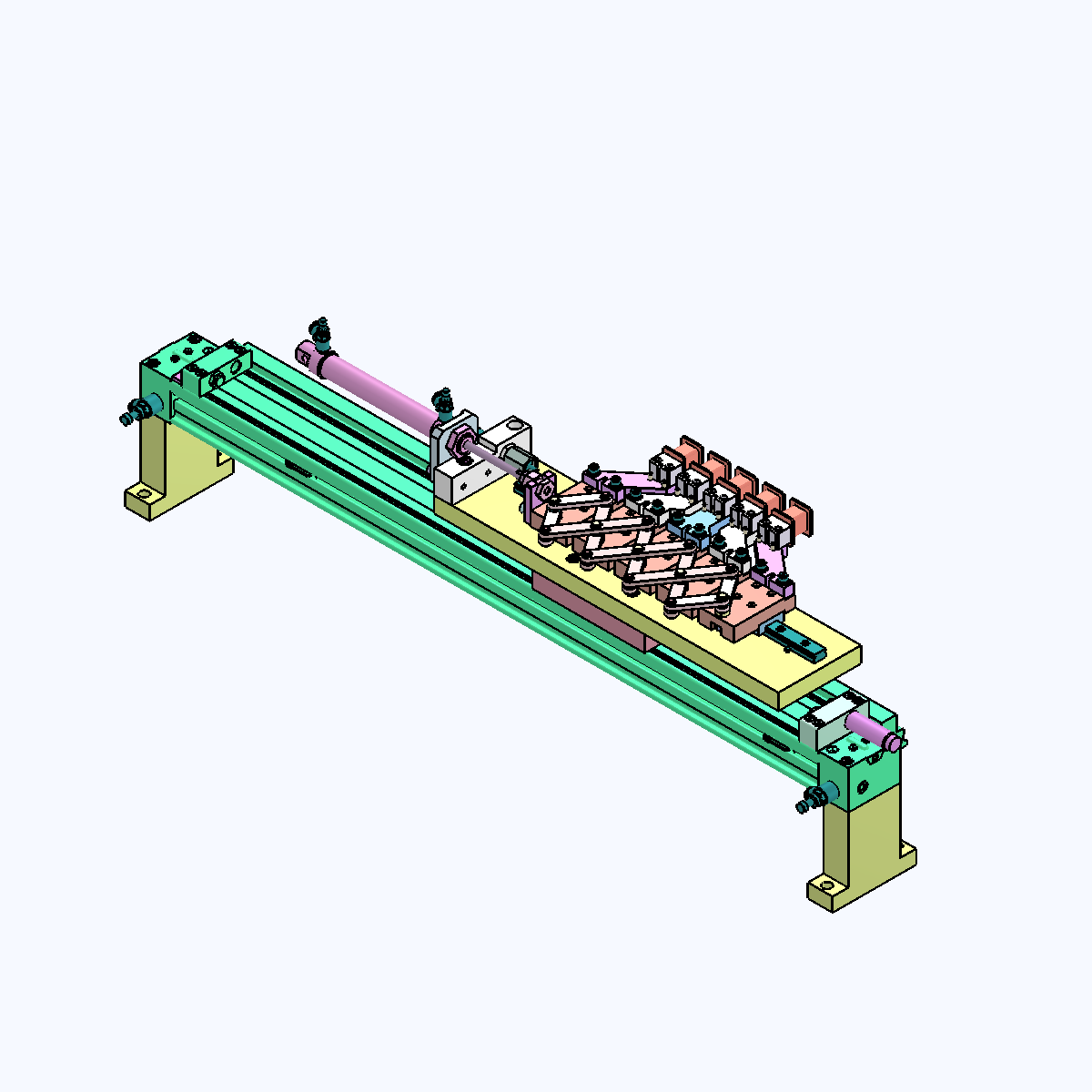
A five-station indexing mechanism is designed around a synchronized pitch-transfer motion and a compact linear-guiding package. The supplied drawing set shows how the base plate, linkage, guide rail, pins, and locating hardware work together as a repeatable indexing assembly. The selected BOM combines PMI linear motion and standard locating components so the mechanism can be assembled, serviced, and scaled with a consistent component record.
Drawing coverAssembly view
Stations5
MotionIndexing
BOM lines50
FormatSTEP
BOM Preview
First ten component lines
#
Part No.
Description
Qty
Type
1
—
Fixed base plate
1
Machined
2
—
Slider link block
5
Machined
3
—
Connecting rod
6
Machined
4
MDD12-6-Y4-F8-E12
Cantilever pin
5
Standard
5
MIC14-D5-L10
Hinge pin
8
Standard
6
IAC11-H13-L305
Linear guide
1
Standard
7
_IAC11-H13-L70-002
Custom guide assembly
6
Machined
8
UAJ02-WASHER
Precision washer
5
Standard
9
UAJ02-WASHER
Precision washer
8
Standard
10
—
Connecting rod
4
Machined
The full supplier BOM contains 50 lines. Download the STEP file above to inspect the complete assembly in any CAD viewer.
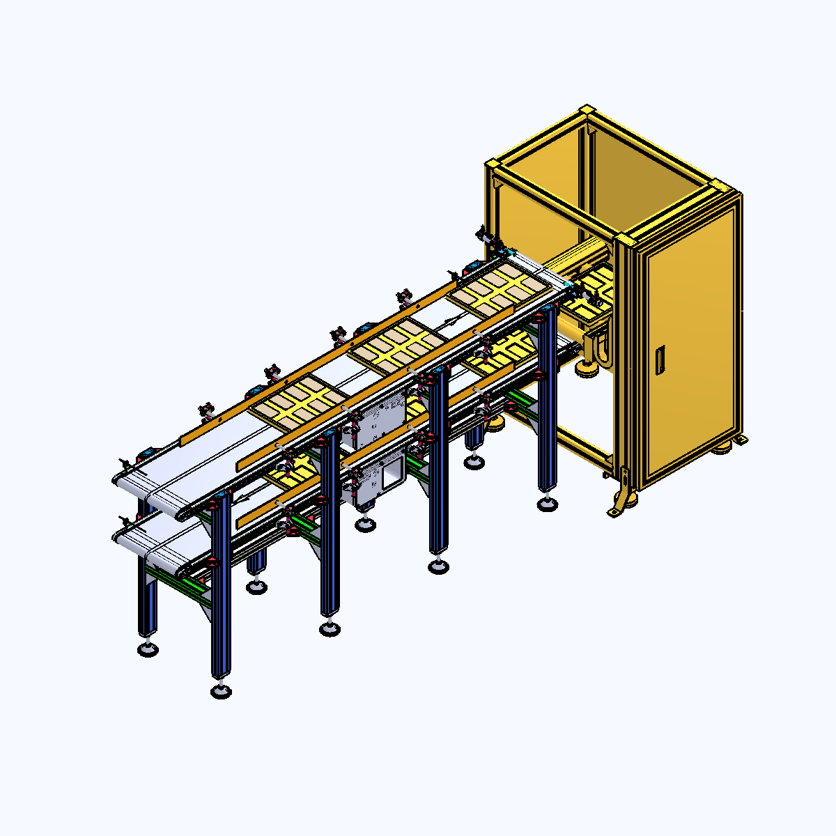
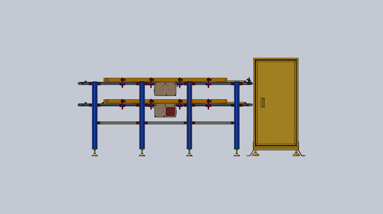
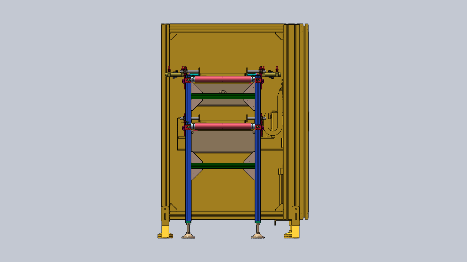
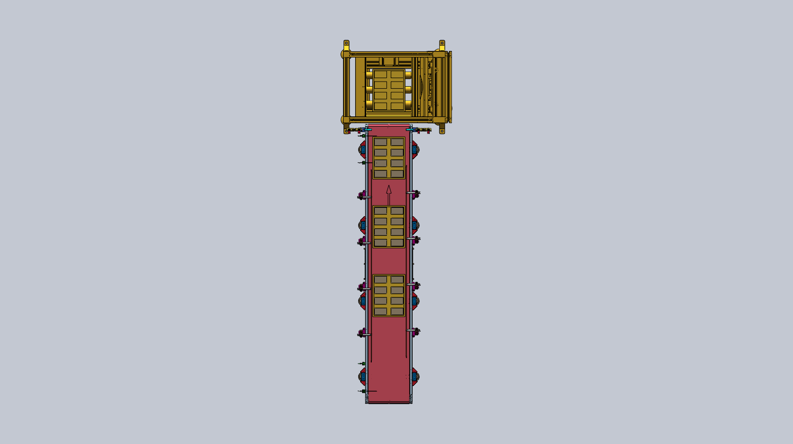
This cyclic material-tray lift combines an aluminum profile frame, belt conveyor, lifting module, guide shafts, and a compact pneumatic circuit. The supplied views document the full material path from the conveyor section to the raised work position and back again. Its BOM reflects the practical mix of standard motion, conveyor, profile, and locating parts needed to make a compact handling cell easy to procure and maintain.
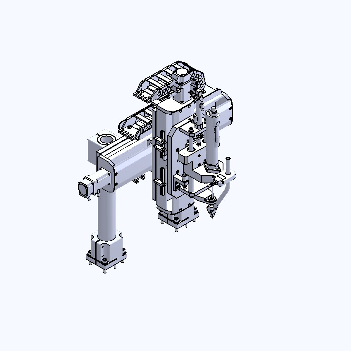
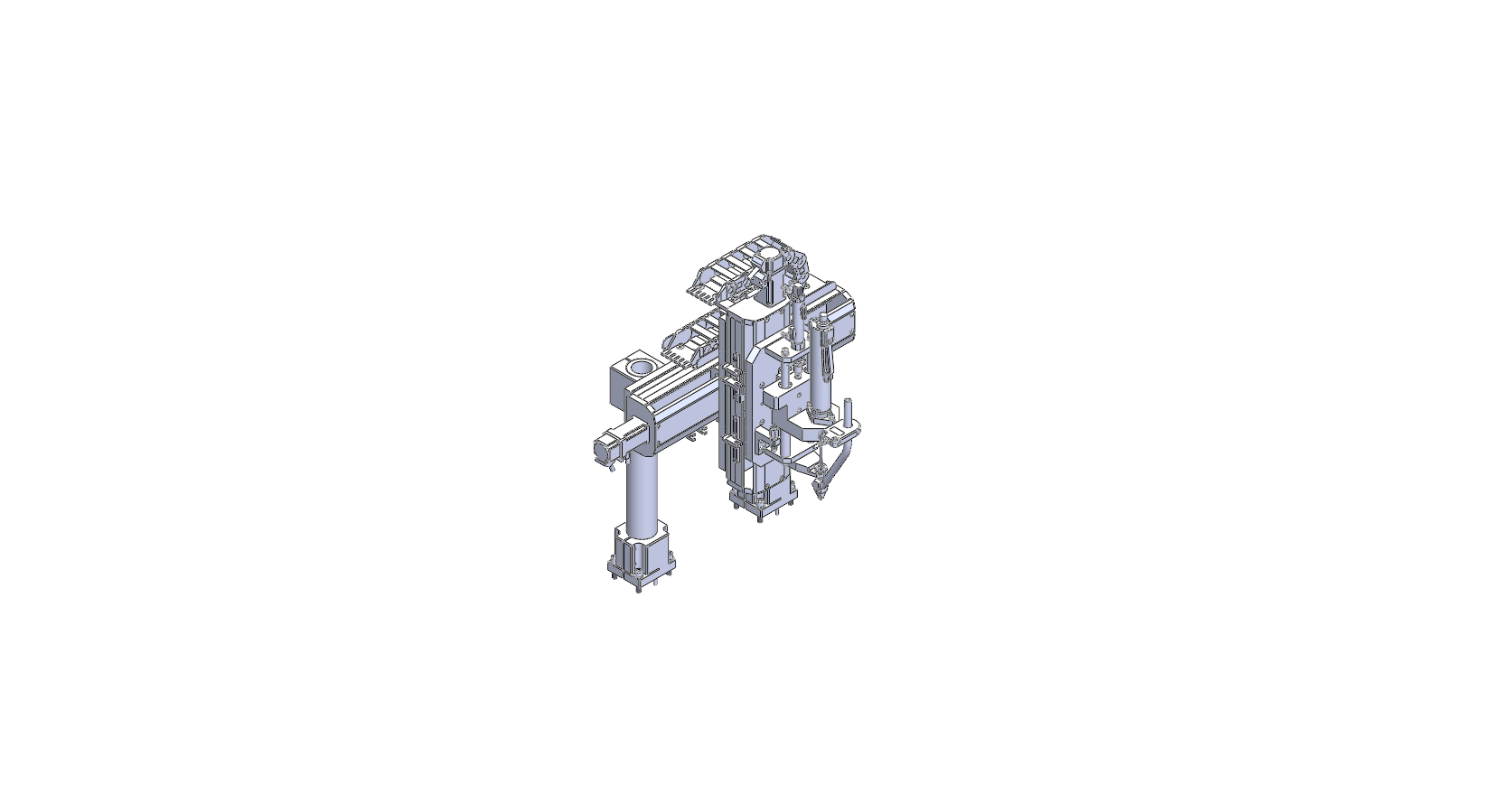
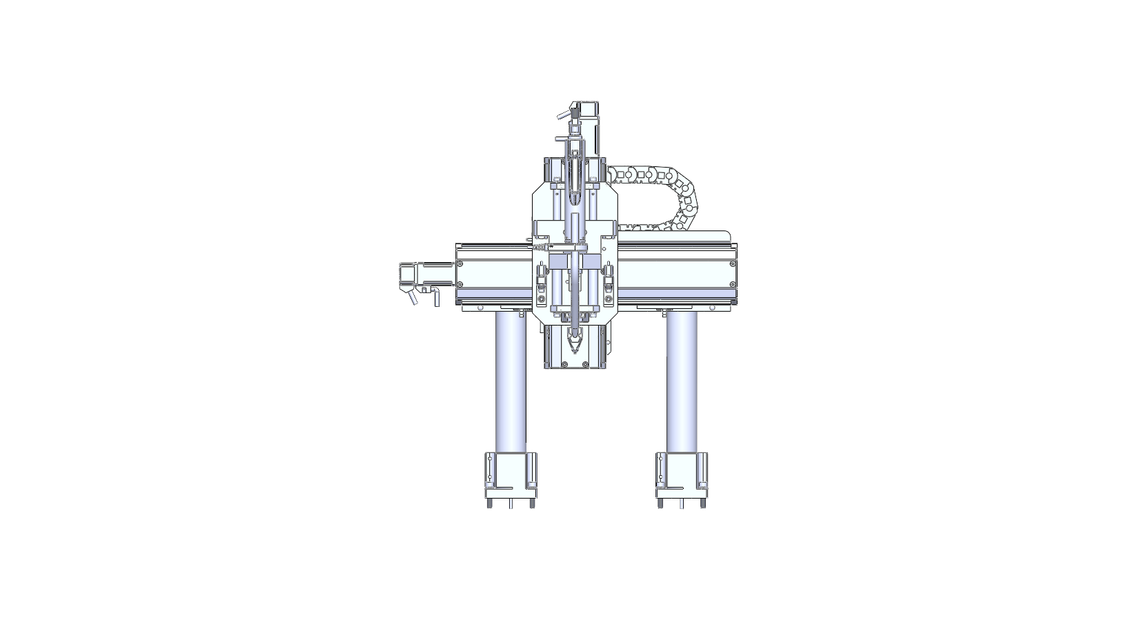
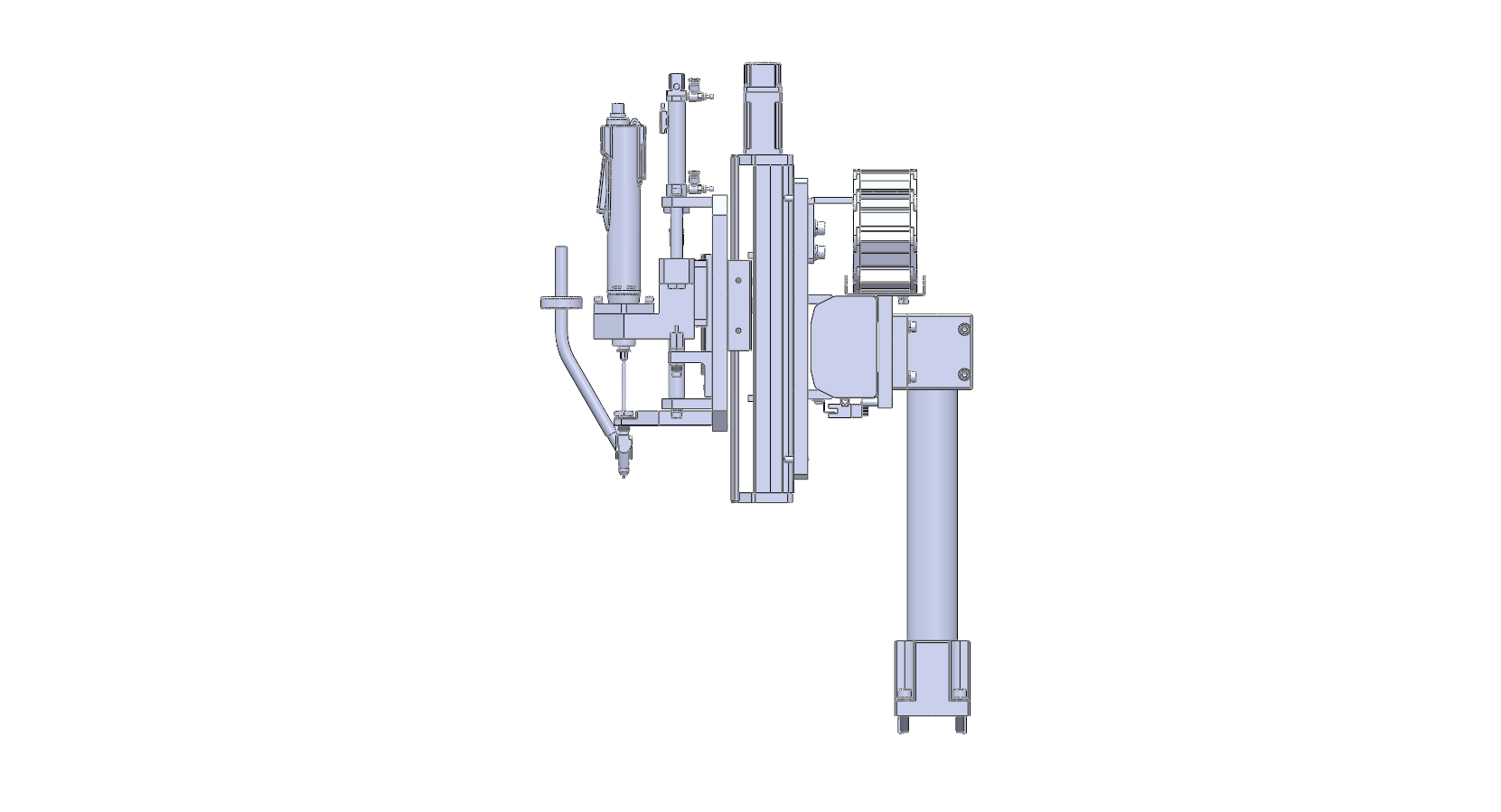
This three-axis screw-fastening cell coordinates a horizontal transfer axis, a vertical lifting axis, and a screw-driving head around a dual-workpiece fixture. The supplied drawing set shows the chuck, electric screwdriver, guide shafts, linear bearings, cylinders, sensors, and drag-chain supports arranged into a compact assembly. The 64-line BOM makes the integration boundary clear and gives procurement teams a practical starting point for component sourcing.
The full supplier BOM contains 64 lines. Download the STEP file above to inspect the complete assembly in any CAD viewer.
3D Model Previews
Inspect the assemblies after the drawings.
Each STEP viewer below loads only after the page and all engineering images are ready. Files are fetched once, cached, and rendered with a progress indicator.
01Multi-Station Indexing
STEP · approx 4 MB
02Material Tray Lift
STEP · approx 5 MB
033-Axis Screw Machine
STEP · approx 6 MB
Have a similar project?
Send us your STEP and XLSX files. Our engineers will review the BOM and recommend a sourcing path within 24 hours.